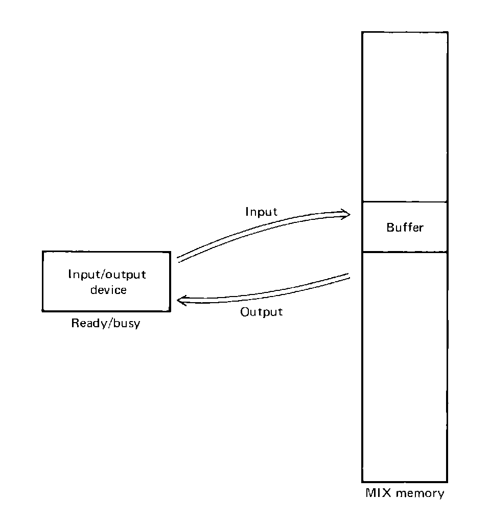
 FIGURE 5.1 The relationship between an I/O device and an I/O buffer.

A very important part of assembly language programming deals with the input and output of information to and from peripheral devices. The programming techniques of Chapter 4 deal mainly with the computing aspect of programming, but this aspect is useless unless data can be input for computation and the results of computation can be output for examination and use. In this chapter, we present some of the basic techniques for input/output programming.
As with the techniques of Chapter 4, the concepts discussed in this chapter are generally applicable to most computers. However, the specific instructions or instruction sequences for coding these techniques will vary with the instruction set, input/output system and devices available on a given computer. Each computer and each problem will need to be considered for its own properties.
Input/output for most modern computers is asynchronous. This means that the timing of the operation of the central processor and each I/O device is independent. The central processor is internally synchronous; each action is controlled by the control unit and each action is performed at exact specific times as determined by a central clock in the CPU. Every operation in the CPU occurs at well-specified times and the duration of each operation is exactly specified in terms of the number of ticks of the clock needed for that operation.
With input/output devices, this is not true. The input/output instructions (IN, OUT, IOC) only initiate an operation; the actual operation takes an indeterminable time depending on the nature of the I/O device, its state, and the operation. This is caused by the physical nature of the I/O devices and the necessity of mechanical operation in order to perform I/O functions. Mechanical operations simply cannot be built to the rigid timing specifications that electronic circuits can be built to. This uncertainty requires careful consideration of the way in which I/O devices and the CPU interact. Physically, this is done by building, for each device, a controller. A controller is a piece of electronic circuitry which controls the attached I/O device for the CPU. A controller may well be a small computer (a microcomputer or minicomputer) programmed exclusively for this purpose, or it may be a special-purpose device designed and built specifically as a controller. The CPU sends commands to the controller to perform I/O, and the controller sees that it is actually done.
The actual input/output instructions for the MIX computer are limited to only three: IN, OUT, and IOC. For each of these, the F field of the instruction (byte 4) specifies the unit number of the device which is to be used for the I/O. The effective address calculated from bytes 0:3 (the address and index fields) is used as a parameter for the instruction. For the IN and OUT instructions, the effective address is the address of a buffer in memory which should be used in the transfer of information between the I/O device and memory. The IN instruction initiates the input of information into memory, storing in the memory locations beginning with the effective address and continuing for one record. The previous contents of the memory locations used by an IN instruction are destroyed by the storage of the new information. The OUT instruction sends information to an output device. The information is transferred from memory, beginning at the address specified by the effective address of the OUT instruction. Since the contents of memory are simply read and sent to the I/O device, the contents of memory remain unchanged.
For both the IN and OUT instructions, the amount of memory transferred is determined by the I/O device selected. Each IN or OUT instruction begins the transfer of one record of information. A record is the (physical) unit of information which is naturally handled by a device. The record for a card reader or card punch is one card; for a line printer, one line. Thus the size of a record for a card reader or card punch is 80 characters long; for a line printer, 120 characters long. Since 5 characters can fit in one word on the MIX computer, this requires 16 words of memory for a record of a card reader or card punch, and 24 words for a record of a line printer. The magnetic tape, disk, and drum devices for MIX computers all have records of 100 words. The typewriter and paper tape unit has 70-character (14-word) records.
 FIGURE 5.1 The relationship between an I/O device and an I/O buffer.
Note that these record lengths need not be true for all card readers, punches, line printers, tapes, disks, drums, or terminals. There exist card readers and punches which deal with cards of 51 or 96 characters instead of 80. Line printers have been built to handle lines of 80,12 0,132, or 136 characters (among others). Many teletypewriters, CRT terminals, and paper tape devices handle data one character at a time, with line lengths of 70, 72, 80, 120, 132, or 136 characters. In this text we will consider only the standard MIX input/output devices. If your installation has non-standard peripherals, special attention may be necessary on your part in their programming, but the concepts presented here will still be applicable.
Since an IN or OUT instruction only starts an operation, at any time each device may be in either of two states: ready for a new command, or busy with a previous one. Each device alternates between these two states. Initially, the state of the device is ready; it is waiting for a command to do something. When the CPU executes an I/O instruction which selects this device, the device begins work on the task which it is assigned, becoming busy. After as long a time as needed to perform the task requested of it by the CPU, it finishes and becomes ready again, able to perform another I/O command. One bit for each device records the state of the device, as ready or busy. The setting and clearing of this bit are controlled completely by the device.
The ready/busy bit is used in several ways. First, it may be tested by the JRED and JBUS instructions which can be used to control the execution of the CPU. The JRED and JBUS instructions specify a device unit number in their F field, and will jump to the effective address if the device is ready (JRED) or busy (JBUS). The state of the device is not affected in any way.
The other use of the busy/ready bit is in controlling the IN, OUT, and IOC instructions. When an IN, OUT, or IOC instruction is decoded by the control unit, it will mean that a new I/O command is to be issued to the (controller of the) device specified by the unit number given in byte 4 of the instruction. If that device is ready, the new command can be issued and the CPU can continue to the next instruction. If the device is busy, however, the new command cannot be issued. I/O devices (and their controllers) are generally rather simple devices and so they can only do one thing at a time. Because of this, it is only possible to have one outstanding I/O request per device at a time. If the control unit decodes an I/O command (IN, OUT, IOC) for a busy device, it must wait until that device becomes ready before it can issue the new command.
Thus, if a device is ready when an I/O instruction is executed for that device, it only takes one time unit to execute. If, however, the device is busy, the execution time for that instruction can take an arbitrarily long and unpredictable length of time, however long it takes until the device finishes its last command and becomes ready (only to become busy again with the new command). This extra time is called interlock time.
We have discussed the IN, OUT, JRED, and JBUS instructions so far and have avoided mention of the IOC instruction. The IOC instruction is used to provide special-purpose control functions for some I/O devices; its use and meaning is entirely dependent upon the device with which it is used. It is the instruction which allows all of the special device-dependent functions we may need to do but do not really need a separate instruction for. We would like to be able to tell the tape units to rewind, but a rewind command would not make much sense for most other devices. (Rewind a line printer?) The IOC instruction has a different interpretation for each device, and allows us to skip to the top of a page on the line printer, position magnetic tapes forward or backward, move the read-write head of a moving head disk to a new track, or rewind a roll of paper tape. The specific coding of the IOC instruction for each device is covered below when we discuss the programming of each MIX I/O device.
The standard programming for MIX I/O devices varies from device to device. Because of this we give here a short description of the standard programming techniques used for each of the normal MIX I/O devices: card reader, card punch, line printer, magnetic tape, magnetic disk and drum, teletype, and paper tape reader/punch.
These devices are the main source of input for a program. They are all character-oriented and transmit the six-bit MIX character code. The only difference in their programming is in their record lengths. For the card reader, the input record is one card, 80 characters, 16 words; for the teletype and paper tape reader, the input record is one line, 70 characters, 14 words. This affects only the size of the buffer which needs to be allocated and the values of indices used in loops to use the input data. For convenience of explanation, we discuss all of these devices in terms of the card reader. The changes for the other devices only involve changing the device numbers and record lengths.
Input is initiated by the IN instruction. If we have defined a 16-word buffer CARD (CARD ORIG *+16), then we can read a card into it by
While the computer is executing the JBUS instruction, the card reader is reading characters off the card one at a time as they pass in front of the reading station in the card reader. These are sent, one at a time, to the card reader controller. When the controller has five characters, it packs them into one MIX word, sets the sign bit to "+" and stores this word in the next buffer location in MIX memory. The controller has an internal register which is used to remember the address of the next memory location into which the next word will be stored. After each new word is stored in memory, this register is incremented by one. Thus successive five character groups are packed together and stored in successive locations in memory as they are read. Each character may take from 100 to 600 MIX time units to be read. When the entire card is safely placed in memory, the controller sets its ready/busy bit back to ready and waits for a new command from the computer.
All this time the CPU is executing the JBUS *(16) instruction over and over again. When the controller finally sets its state to ready, the jump test fails and we drop out of the wait loop and can proceed to use the newly read card. When we want another card, we can repeat this code.
A programmer must always be very careful that the input device is done with an input operation before attempting to use the data being read in. For example if we were to write
The card reader, teletype keyboard, and paper tape reader are the standard input devices, while the line printer, card punch, teletype printer, and paper tape punch are the standard output devices. As with the input devices, the programming of these output devices varies only with respect to their record lengths and speeds. The record lengths (120 characters for the line printer, 80 characters for the card punch, 70 characters for the teletype printer and paper tape punch) only determine the amount of space needed for the buffers for these devices; thus, we will limit our discussion to the line printer. The concepts apply equally to the other devices.
Outputting to the line printer is essentially the same as reading from the card reader, with the exception that since we are outputting, the programming to create the output line must be programmed and executed before the line is output. Once this is done, and the appropriate character codes are stored in memory -- for example, in a buffer called LINE -- we simply write
An IOC 0(18) will cause the line printer to skip to the top of a page. IOC 0(19) will rewind the paper tape. IOC has no effect on a card reader or card punch.
The main effort in I/O programming for these devices is not the actual I/O but rather in the conversion between numeric and character code representation of data, and formatting input and output. The format of our input and output is simply a statement of what it looks like.
For input, the format of the data is the form in which the data is expected to be by the program which is inputting the data. Examples: two decimal integer numbers, one in columns 4 and 5, the other in columns 9 and 10, with all other columns blank; or a 10-character name in columns 1 to 10, with a description of any kind (i.e., any sequence of characters) in columns 15 to 72, columns 11 to 14 should be blank. It is the problem of the programmer to interpret this input correctly. This generally becomes a problem of character manipulation. The only help that MIX offers is the NUM instruction. If a character code representation of a number (up to 10 characters long) is put into the A and X registers, the NUM instruction will convert this to numeric binary and put the result in the A register. The signs of both registers and the contents of the X register are unchanged. An example of the use of this instruction: Suppose we have a number punched in columns 11-20 of a card. To read it and use it, we write
What happens if columns 11-20 have non-numeric punches? The NUM instruction works anyway, by treating each character, numeric or not, as having a value equal to the units digit of its character code expressed in decimal. Thus the characters "A", "J", "1", comma, and ">" all have a value of 1 for the NUM instruction, while "B", "K", "S", "2", "(", and "@" have the value 2.
For output, the conversion is performed in the opposite direction, numeric to character code, by the CHAR instruction. If we have a number in the location NUMBER, we can convert it to character code and print it by
The CHAR instruction converts a numeric integer in the A register into a 10-byte decimal character code representation. This character representation can be stored into an output line image and printed. Note that the programmer has complete control over where in the output line the characters to be printed are put. The format of the output line is determined by the programmer. The preparation of the output line may involve some character manipulation.
The I/O devices which we have considered so far have been for the input and output of character representation of data. Magnetic tape, on the other hand, is basically a storage I/O device. Information can be written to tape and then read back into the computer, but it is very difficult for a human to either read or write magnetic tape. Because of this, programming of magnetic tape devices differs from the devices which we have already considered.
The writing of information to a tape is done by the OUT instruction as
The magnetic tape at any given time has a number of records on it. Each time a new record is read or written, the tape moves so that the read-write heads are positioned after the most recently read-written record and before the next one. Typical use of a tape is to write out successively a number of records. Then the tape is rewound and the records are read back in.
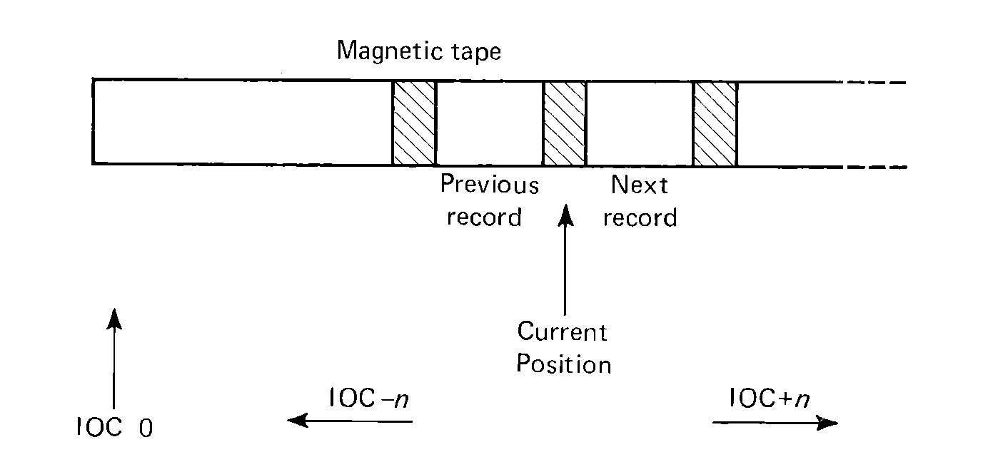 FIGURE 5.2 Magnetic tape usage
on the MIX system.
The IOC instruction is used to position the tape, relative to its current position. The effective address, M, is used to specify the direction the tape should be moved. If M is less than zero, the tape is moved backwards; if M is greater than zero, the tape is moved forward. The magnitude of M specifies the number of physical 100 word records to move. Thus, IOC -1(2) moves tape unit number 2 back one physical record, while IOC +3(1) moves tape unit 1 forward 3 records. IOC 0(n) would mean to not move the tape (forward or backward) and hence is meaningless, so this code (effective address = 0) is used to mean to rewind the tape. To position a tape just before the first record on the tape, we would simply IOC 0(n); if we wanted to position before the second record, we would IOC 0(n) and then IOC +1(n).
Since the effective address is used to determine the positioning it can be indexed. This allows code like the following to be used. Assume that index register 4 contains the number of the record before which we are currently positioned on tape unit 5 (after a rewind, register I4 would contain 1, and after each read I4 would be incremented by one). Index register 1 contains the record number of the record we want to read in next. Then we can execute the following code to position tape 5 correctly
Remember that, because of the nature of magnetic tape, a write (OUT) instruction destroys all information from the point of the write to the physical end of the tape. Hence, at any given time it is possible to read only as far as the last record written; the remainder of the tape is garbage. This constraint applies to positioning also. The tape cannot be positioned beyond the end of the most recently written record on the tape.
Magnetic tape is by its nature a sequentially accessed device; records are accessed from the beginning to the end, one at a time. This is due to the physical nature of the device. Disk and drum storage devices have been constructed to allow any given record to be directly accessible, however, so these are called direct access, or sometimes random access devices, as opposed to the sequentially accessed magnetic tape devices.
The differences between disks and drums are mainly physical. A drum is constructed as a recording surface on the side of a cylinder, while a disk unit has perhaps several flat disc-shaped objects with recording being done on both the top and bottom surfaces of each disk. Each device has a number of tracks which are broken up into 100-word sectors. There are 4096 sectors per device. Each sector corresponds to a record for that device: 100 words (including sign).
The real difference between these two types of devices concerns how the read-write heads are used. Just as with magnetic tape, it is necessary to move the recording surface past a read-write head to convert between the magnetic form of information on the disk/drum and the electronic form of information used in the CPU. This is accomplished in two ways. In the one case, usually used for drums, each track has its own head. This is known as a fixed-head device. When a particular record is to be read or written, the head for that track is selected and the device controller waits until the sector for that record rotates beneath the heads, then the data is transferred (to the device for a write; to memory for a read). The time waiting for the device to rotate is called latency time; the time for the actual read or write is called transfer time.
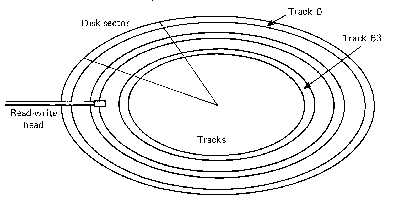 FIGURE 5.3 Disk structure for the MIX system. Each disk
has 64 tracks, with 64 sectors per track.
This architecture can be very expensive. With one head per track, a drum with 200 tracks requires 200 read-write heads, and heads are not cheap. The most common solution to this is the moving-head device (generally a disk). In these devices, there is only one head per surface (for a single disk platter, this requires two heads: one for the top surface and the other for the bottom). The heads are attached to a movable arm. An I/O operation requires several steps. First the heads are moved to be over the desired track. This is called a seek operation, and the time to perform it is seek time. Once the head is positioned over the correct track, the controller waits until the correct sector rotates under the head (latency time) and then begins the requested I/O operation (transfer time).
For either fixed-head or moving-head devices, every I/O operation must supply the addresses of the locations involved in the transfer: the address of the memory buffer of 100 words in MIX memory, and the address of the sector to be used. The address in memory is the effective address given in the IN or OUT instruction; the address on the disk/drum is specified by bytes 4 and 5 of the X register. When the IN or OUT instruction is executed by the control unit for a disk or drum, the contents of the lower two bytes of the X register are copied into the disk/drum controller which then performs a seek operation (if the device is moving-head), waits for latency, and finally performs the transfer. This can be programmed by
In this code, we output to each successive physical record on the disk. To read this information back into memory, we simply set DISKADD back to zero and read back in from the same disk addresses that we wrote out to, incrementing DISKADD after each read, of course.
Disk records need not be accessed strictly sequentially either. In an information storage system for names, we might store all names starting with "A" in records 0 to 9, all names starting with "B" in records 10 to 19, and so on. Then, to update a record for a given name, we can write
An IOC for a disk or drum initiates a seek instruction. The seek time for a moving-head disk or drum can be quite long, on the order of 10 to 100 milliseconds, and much longer than either latency or transfer time. Because of this, it is sometimes possible, and advantageous, to seek ahead by moving the head to the track which contains the sector to be used next, so that the head will already be there before the actual IN or OUT is issued. The effective address of the IOC should be zero. The track to seek to is given by bytes 4:5 of the X register. An IOC for a fixed-head disk or drum is ignored, since no seek is needed. For example, to access records sequentially
Consider a simple, but useful problem: we have a deck of cards and we wish to copy them from the card reader onto the line printer in order to get a listing of them. In order to do this, we must first read a card, then print it on the line printer, read the next card, print it, and so forth until the last card is read.
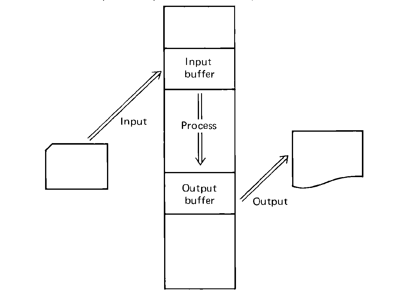 FIGURE 5.4 Input/output structure -- basic structure of
a simple program to input data, process it, and output the results.
How do we tell when the last card is read? The MIX card reader has no way of telling the CPU that there are no more cards, so we must find some way to mark the end of our input. This will be done by an end-of-file card, a special card which marks the end of our deck. Since it is easy to compare an entire word at once, we will use a card with *EOF* in columns 1-5 to mark the end of a card deck. We could use any set of letters in any columns, but we want to avoid any end-of-file marker which might be expected to occur in the input. If the input to be listed were to accidentally contain the end-of-file marker as part of the normal deck, the listing would stop prematurely, which can be most frustrating. Thus we do not want to interpret a card which is blank in column 1 as the end-of-file, since this is very likely to happen in most decks.
Now that we have made this decision, we can begin to write our program. The general flow is:
This program shows the basics of reading from the card reader and writing on the line printer. To input from a device, first define an array as large as the record for that device as
A number of improvements of the above copy program are possible. First, notice that there is no need to move the input card from CARD to LINE; we can output directly from our input buffer (or input directly into our output buffer). Second, the *EOF* constant is used to compare against the first word of the input record, which requires loading one of them into the A register (or the X register). In the above, we chose to load the first word of the input. If we load *EOF* instead, it need never be reloaded, since the A register is not used for anything else. Third, notice that the above card-reader-to-line-printer copy program will work equally well for a card-reader-to-card-punch copy program if we simply change the unit numbers. In fact, the unit numbers are only an artifact of the standard unit numbers assigned by the factory; they may be changed for another MIX computer system. For these reasons, it is better to use symbolic constants for unit numbers rather than numeric unit numbers.
With these modifications, we can rewrite COPY as
A slightly more complicated program will also give us line numbers for each line, to give us a count of the number of cards read. Noticing that (for a card-to-printer copy) each input record is 80 characters, while each output is 120, we have 40 columns of spacing and line numbers to use. Assuming that no more that 99,999 cards will be listed, we only need a five-character line number. Thus, we can format our output line as
| Columns | 1-5 | blank | |
| 6-10 | line number | ||
| 11-15 | blank | ||
| 16-95 | input card image |
For this program, we must introduce a counter and instructions to convert the counter from binary to character code for output. We can still read our card directly into the locations used for the output buffer, and most of the above program remains the same.
In this program, we have done several things differently. In addition to numbering the cards, we have added special code to print the number of cards read (excluding the *EOF* card) after the listing, separated from it by one blank line. Notice that we are outputting from three different output buffers and that a JBUS is not needed after the OUT BLANK since the OUT EOFLINE(LP) will automatically wait for it to finish. Some local optimization can be done. The last CHAR sequence (in EOFOUND+1 and EOFOUND+2) is unnecessary, since the character code for COUNT is still in the X register from the previous output. The CHAR destroys both the A and X registers, which prevents keeping the EOF marker in a register for comparison, and since the index registers can only count to 4095, they cannot be used to store the counter (which can be as large as 99,999).
Local optimizations can only decrease the time to execute by microseconds or milliseconds, however. An entirely different form of optimization is needed to produce an effective speed-up in a program such as the above COPY routines. Consider our second, and shortest, COPY program. The loop which copied cards consists of IN, JBUS, OUT, CMPA, JNE. Thus the execution time for this program is the number of cards times (five time units for the IN, OUT, CMPA, and JNE plus however many times the JBUSs are executed). The time to execute the JBUSs is essentially the time to read a card and print a line.
If we assume that we have a fast card reader, we can read 1000 cards per minute, or one card every 60 milliseconds. If a MIX time unit is 1 microsecond, then it takes 60,000 time units to read a card. A slower card reader (like 300 cards per minute) will take longer (like 200,000 MIX time units). Line printer times are comparable. This is to emphasize that mechanical input/output operations are extremely slow, compared to electronic computing speeds. Programs such as the above COPY programs will spend only a very, very small fraction of their time doing any computation; the rest of the time is spent waiting on the I/O devices. These programs are known as I/O-bound programs. Many data processing and business application programs are I/O-bound. Many scientific programs, on the other hand, may input and output only a small amount of data, but may spend large amounts of time computing. These programs are compute-bound or CPU-bound. There are also programs which are neither I/O-bound nor CPU-bound, but so few that there is not even a special name for this kind of program.
Most programs do at least some I/O, and since I/O is so incredibly slow, it is necessary to try to take advantage of time spent waiting for I/O to perform other, more useful tasks. This results in I/O overlap. There are two kinds of overlap: I/O-I/O overlap, and CPU-I/O overlap. I/O-I/O overlap is the result of programming to try to keep several I/O devices busy at the same time, by overlapping the time to input or output on one device with the time to input or output on another device. CPU-I/O overlap tries to overlap the time to compute something with the time to perform input or output. An efficient program will often use both.
As an example of I/O-I/O overlap, consider the second COPY program
| 3 + n × (5 + r + p) |
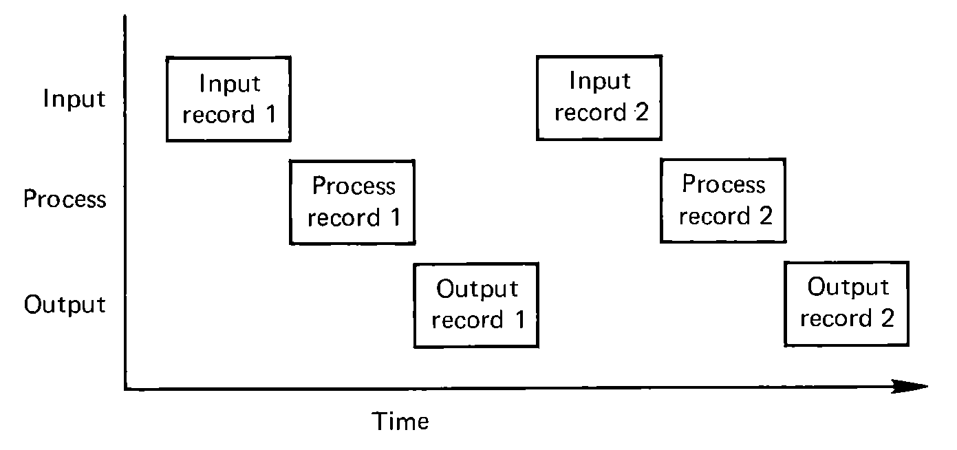 FIGURE 5.5 A time chart of the
execution of a simple program with no overlap of I/O with other I/O or
processing.
Now suppose we notice that while this program is executing both the card reader and the line printer are idle half the time. To read n cards takes only n × r time units, so if the total program takes 2 × n × r time units, the reader must be idle (i.e., ready, not busy) the other n × r time units. Similarly for the line printer. Since these I/O devices are the slowest units in the system, they are the bottlenecks. Hence, we want to keep them busy as much as possible. Our approach is to keep both units busy all the time. This is done by a program which executes like
| 1. | Read first card. |
| 2. | Next, read the second card, and print the first card at the same time. |
| 3. | Read the third card and print the second card at the same time. |
| … | |
| n. | Read the nth card and print the (n-1)st card at the same time. |
| n + 1. | Print the nth card. |
The implementation of this idea can take many forms. First, we note that since we are reading and writing simultaneously, we must have two separate buffers, one for reading and the other for writing. This results in the necessity of moving our input card from the input buffer to the output buffer as
In this program, we move the input out of the input buffer as soon as possible (as soon as it is read and the previous one is printed), and begin the input of the next card immediately. Similarly, as soon as the previous output is complete, we move the next line into the output buffer and start to print it. This keeps both units busy almost all the time.
What does this do to our execution time? Well, the first card is read by itself and the last card is printed by itself. However, the reading of the last n - 1 cards and the printing of the first n - 1 lines overlap almost completely (the input actually starts one instruction ahead of the output). Thus, rather than taking 2 × n × r time units, the program now takes only r + (n - 1) × (max(r,p) + m) + p, where m is the amount of time it takes to move the record from the input buffer to the output buffer (33 units in this case). If p is approximately equal to r and m is very small, compared to r, then this is approximately (n + 1) × r and for n greater than just a few cards, we have effectively cut the execution time for the copy approximately in half. Not completely half, but almost.
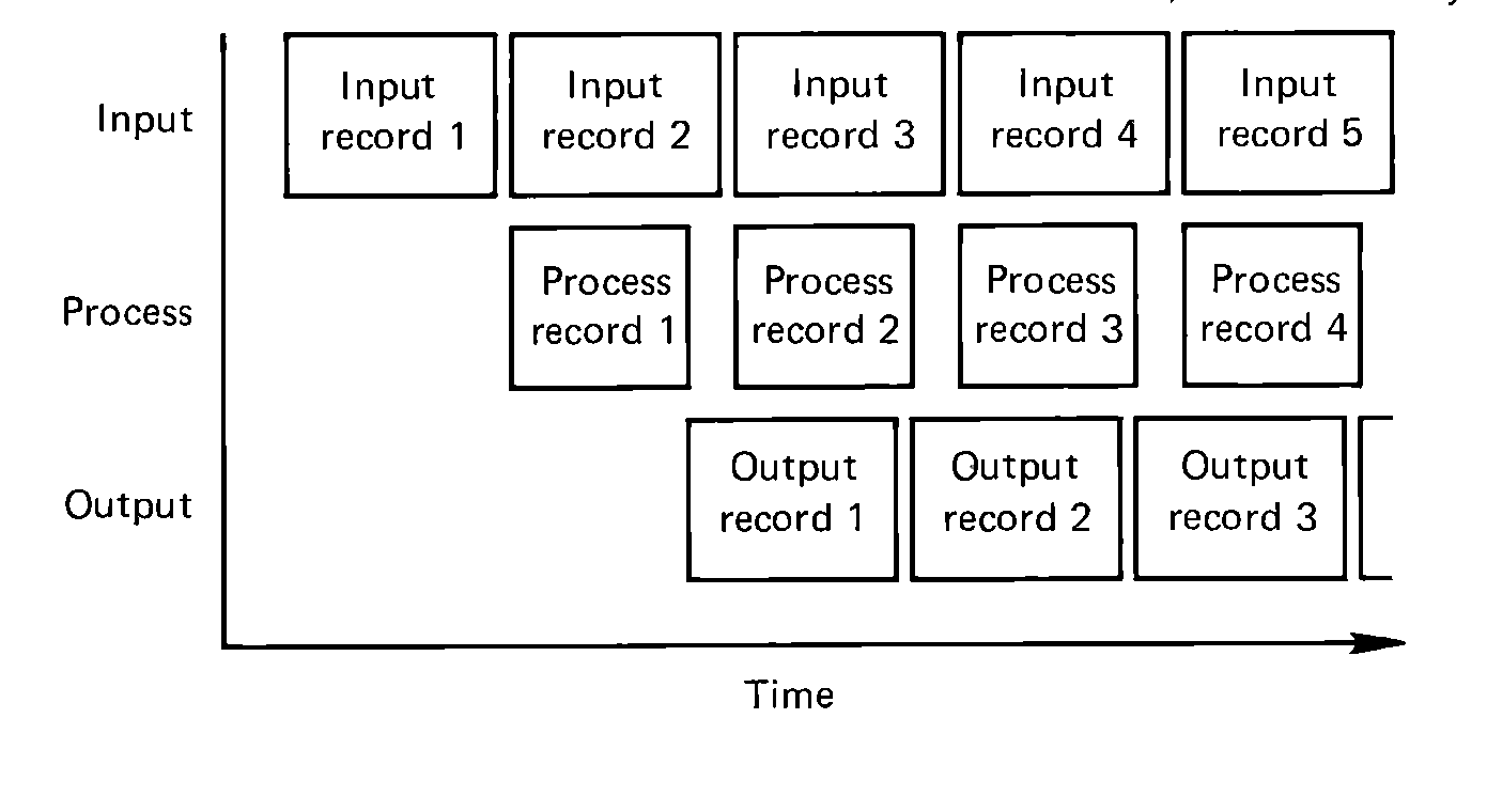 FIGURE 5.6 A time chart of the execution of a program with
overlap of I/O with other I/O and processing. Note that each
record must still be input, processed, and output, in that order;
but at any given time we can work with three different records,
simultaneously.
There are other techniques for the same basic idea. Notice that the time it takes to move the data from one buffer to another cannot be overlapped. As with some of the previous programs, it is faster if we just read directly into the locations where we wish the data to be rather than reading into a buffer and then moving it. Rather than moving the data to (or from) the buffer, we simply use a different buffer. For this simple COPY, we need two buffers, one for input and one for output, but now when input is complete for one buffer, we immediately start to output from that buffer and then input into another buffer. When this second input is complete, we can output it and begin to input back into our first buffer again, and so on. This can be coded as
Notice that in this program we have taken advantage of the way that an OUT automatically waits for a previous OUT to be complete so that we may begin the next output and, as a side benefit, reuse the old output buffer as the new input buffer.
An advantage of this approach is that the MOVE is no longer necessary, and so the total time to copy a deck is less than for the previous versions with the MOVE. A disadvantage is the necessity of writing almost two complete sets of code, one for when we are inputting into BUF1 and outputting from BUF2, and almost the same code for when we are inputting into BUF2 and outputting from BUF1.
This latter disadvantage can be overcome by taking advantage of the effective address calculation of the MIX computer. The only real difference between the two sets of code written above is in the addresses, which differ. We define two variables INBUFADD and OUTBUFADD which will contain, in bytes 1:2, the address of the buffer which is being used for input (for INBUFADD) and for output (for OUTBUFADD). When we want to input, we use indirection to indicate where the next card should be read
An alternative implementation of the same method is to use indexing instead of indirection. In this version, we use index register 5 to point to the input buffer and index register 6 to point to the output buffer.
The COPY program we have been studying is a very special case demonstrating I/O-I/O overlap. More generally, some computation will need to be done on the input before it can be used as output. Thus, in addition to trying to do input and output simultaneously, we will also try to do computing at the same time. If we consider the time involved, let I be the time to do the input, C the time to do the computing, and O the time to do output. If we input a card, compute on it, and then output the card before going back to read another card (no overlap), then the total execution time will be on the order of I + C + O for each card. If, on the other hand, we read a card and, while computing on that card, we also read the next card, and while printing the first card, are computing on the second and reading the third, then the total time will be more like max(I,C,O) per card. This will require at least three buffers, one for input, one for computing, and one for output. The data can be moved between buffers, or the buffers can be swapped, using index registers or indirection to point to the appropriate buffer for each activity. An example is the following program, which counts the number of blank spaces on a card, stopping when an *EOF* card is read.
Computer programs are not restricted to just being of the form: "read a card, compute on that card, print a line of output," however. The program may read several cards before outputting anything or may output many lines while reading nothing. Still, we can attempt to overlap any required I/O as much as possible. All of the programs we have studied so far read into a buffer, and output from a buffer. For sequential devices, such as card readers, card punches, line printers, and magnetic tapes, we can use buffering to overlap our I/O time with computation time. Buffering is simply reading or writing with one buffer while other processing is being done with another buffer.
Double buffering is the simplest case of buffering. In double buffering, we have two buffers for each device. For input, we take our input out of one buffer while the other is being read into by the input device. When the one buffer is empty, we wait until the other buffer is filled (JBUS *) and then start the input of the next record into the empty buffer while we use the newly read one. This can be done either by moving from the one buffer into the other, or merely by switching pointers. For output, we place our output image in one buffer and when this is full, we begin its output (OUT) and immediately begin to place our new output into another buffer. When this new buffer is full we wait for the previous OUT to finish (JBUS *) and then OUT from the newly filled buffer while our program fills the newly emptied buffer with new material to be output. This results in programs such as
Note that buffering may not be possible for input from direct access devices like disk or drum, since accesses on these devices are not likely to be sequential. This means that it is not possible to buffer ahead on input by reading the next record (since we do not know what the next record will be). It is still possible to buffer behind on output, however, since we do know where the last record should be output.
Another problem which arises from direct access devices is efficient storage utilization. Suppose we wished to copy a deck of cards from the card reader to the line printer, backwards. This requires storing the entire card deck in the computer until the last is read and then printing the entire deck. At 16 words per card, and only 4000 words of memory, we could only store 4000/16 = 250 cards if we stored them in memory (and then we would have no room for the program). However, if we store them on disk, we could store 4096 cards by putting one card in each disk record. This would result in an input portion of the program such as
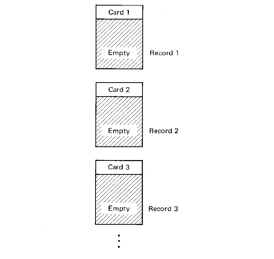 FIGURE 5.7 No blocking -- each logical record
(in this case a card) is stored in one physical record (a disk or tape
block).
However, even this approach limits us to only 4096 cards (only about 2 boxes). Notice that the physical record size for a disk record is 100 words, while a card takes up only 16 words. Thus 84 words of each record are being wasted. We can avoid this waste by packing several card images into one disk record. This is called blocking, since we are then treating several cards as a block. For the situation mentioned above, we can block six cards per disk record easily and increase the number of cards which can be stored to 6 × 4096 = 24,576. The blocking factor is the number of cards per disk record, and in this case is 6.
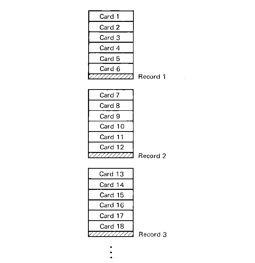 FIGURE 5.8 Loose blocking-multiple
logical records are blocked into each physical record, but no logical
records are split between physical records.
A blocking factor of 6, for card images, still leaves 4 words per disk physical record being wasted. Things could be worse if the size of the information block we wish to store (a logical record) were some other number which does not divide evenly into the size of the physical record. For a 17-word logical record, and a blocking factor of 5, we would use only 85 words, leaving 15 words per physical record wasted. For a 51-word logical record, 49 words would be wasted.
These considerations rapidly lead to the conclusion that it is not always desirable to limit ourselves to only putting an integral number of logical records per physical record (loose blocking), but rather that it is to our advantage, at times, to split a logical record between two physical records. Thus, for 17-word logical records, we put logical records in physical records as
| logical record number | physical record number | words |
| |
|
|
| 1 | 1 | 0-16 |
| 2 | 1 | 17-33 |
| 3 | 1 | 34-50 |
| 4 | 1 | 51-67 |
| 5 | 1 | 68-84 |
| | ||
| 6 | 1 | 85-99 |
| and 2 | 0-1 | |
| | ||
| 7 | 2 | 2-18 |
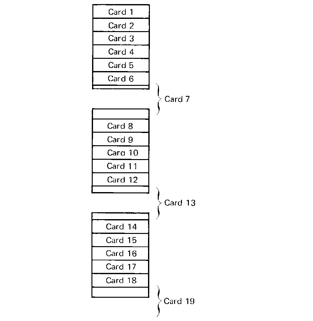 FIGURE 5.9 Tight blocking -- multiple logical
records are blocked into each physical record, and some logical records may
be split between physical records.
Where is a given logical record? Each logical record is 17 words long, so the kth logical record follows the first k-1 logical records and is words 17 × (k - 1) through 17 × (k - 1) + 16 = 17 × k - 1. Since there are 100 words per physical record, the physical record which holds the first word of the kth logical record is physical record number (starting at zero) 17 × (k - 1)/100. The remainder of this division is the word number within the physical record of the first word of the logical record. Thus, it is possible to access a given logical record directly even if we block logical records as tightly as possible.
For sequential access, the problem is much easier to solve. To extract the next logical record from a physical record buffer, we need a pointer which indicates the index of the last word which we have returned (the end of the last record). Putting this in a register, we transfer from the physical record buffer to the logical record buffer, one word at a time, the next 17 words. If the index into the physical record buffer at any time exceeds 100, this means that the physical record buffer is empty and a new record must be read and our index reset to zero before transferring the next word. The MIX code for this is
There are two other points which should be made. First, how do we know where the end of the data on the disk is (particularly since it may end in the middle of a physical record)? One method would be to use a special value for the logical record, such as the *EOF* marker we have used for card decks. As each logical record is used, we can check to see if it is the last one. A variant on this, for the case of alphanumeric character code information stored on the disk would be to use the sign bit (which is always set to "+" by the card reader) to signal the last logical record by setting the sign bit of the first word of a logical record to "+" for all logical records except the last one, for which the sign is set to "-".
A more general idea is to store at the beginning of the physical record a count of the number of information-bearing words in the physical record. If the value of this counter were 37 for a particular record, this would indicate that the first 37 words are valid and the other words (the last 62) are garbage. Notice that this reduces the effective size of the physical record by one word. Also, for most records, the value of this word will be constant (at 99); only the last physical record will have a different value.
The number stored in the first word could also be the number of valid logical records, the number of unused words, the beginning index of the last valid logical record, and so on.
Input/output is a crucial part of most programs, since few programs operate in isolation from the outside world. At least the results of the program must be output, either to a person or for another program or computer. Input/output is basically asynchronous. Each device has a busy state and a ready state. The JBUS and JRED instructions allow this to be tested. The IN and OUT instructions start the transfer of information between the device and the memory of the MIX computer. Each device is programmed using its own techniques. Buffering is used to reduce the real time that it takes to execute a program by overlapping the execution of the CPU and input/output operations and to overlap the operation of different I/O devices. Blocking is a technique for making maximal use of disk, drum, or tape space by packing several logical records into a physical record.
Because I/O is so very slow relative to CPU operations, I/O programming must be very carefully done. Gear (1974), Stone and Siewiorek (1975), and Eckhouse (1976) all have a complete chapter on I/O programming. Knuth (1968) also devotes a section to I/O. These treatments are especially concerned with overlapped I/O.
A very important improvement over the ideas presented in this chapter is the technique of interrupts. Interrupts is a hardware feature which can help with I/O. MIX does not have an interrupt system, so we delay discussion of this topic until Chapter 10, where it will be presented in terms of other computer systems.