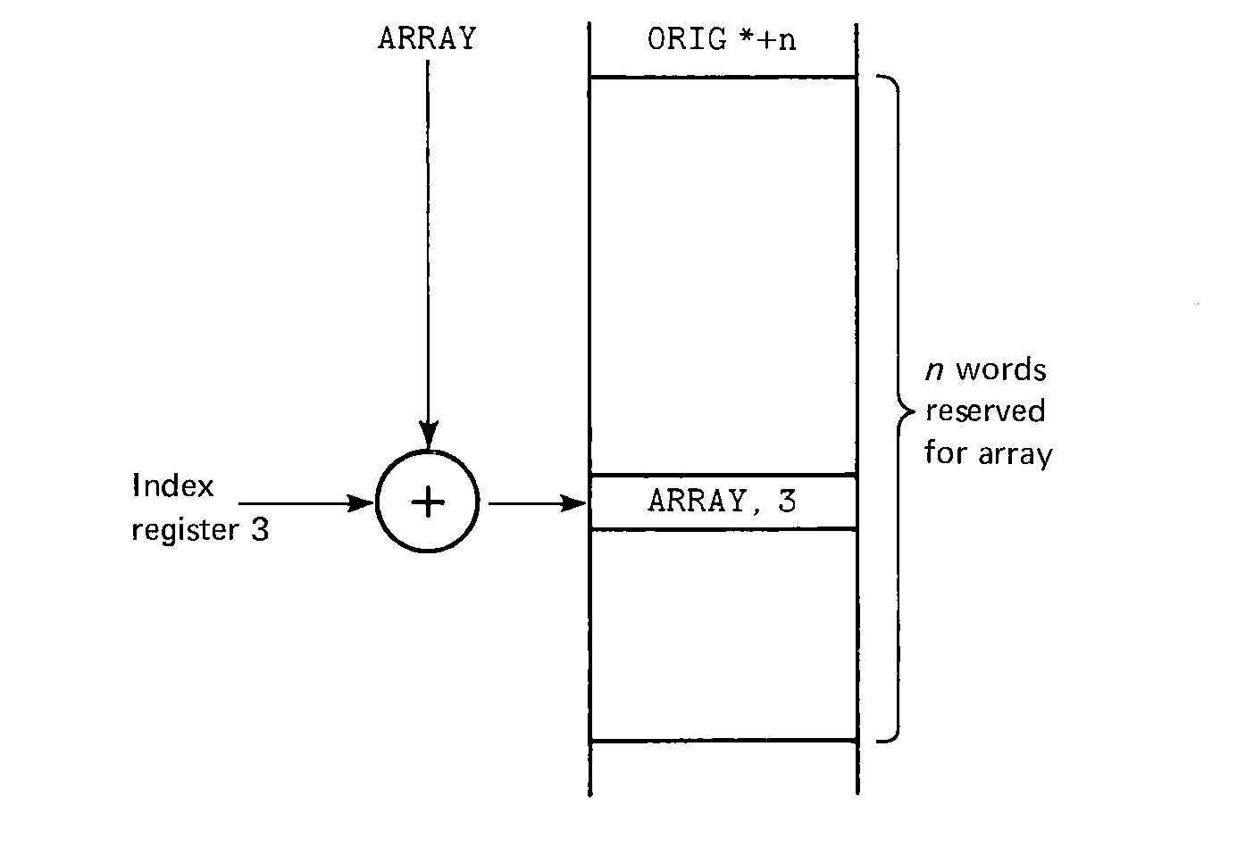
 FIGURE 4.1 Storage allocation and accessing for an array.

In some sense, the programming process is independent of the language which is used for programming, but in a more realistic sense different languages encourage different programming techniques to be used. The machine which is being used for assembly language programming, since it affects the instruction set, also affects the type of programming which can be easily done. The result of this is that there is a body of general programming techniques which can be used for programming in assembly language for most machines, but the details must depend upon the particular machine being used. The basic concepts and techniques are the same for most computers. In this chapter we present some of these techniques to illustrate how to program in assembly language. By and large, many of these techniques will only be learned by their use, however, and as you program you will learn new techniques which are not presented here.
Writing a program is an art, and no one way to program is correct for ail situations. Recent discussions have lead to general agreement on several points, however. First, an important distinction exists between programming and coding. Programming is the process of converting a vague description of a problem into a specific algorithm for solving the problem. This involves defining appropriate data structures, determining what information is to be input and output and the flow of control within the program.
Defining the flow of control can be helped by the use of top-down programming techniques. A top-down approach starts with a general statement of the problem and successively refines its components by considering each of these to be a separate problem. This is somewhat difficult to explain, but easier to illustrate. Look back at how the program to add two numbers together and print their sum, in Section 2.2, was developed. First the top-most level was defined: Input, Add, Output, Halt. Then each step at this level was examined and broken down into its components until each step of the program could be converted directly into machine language. Typically, the top-down refinement process continues until each step can be solved by a single machine language instruction, subroutine (see Chapter 6), or macro (see Chapter 9).
The translation of each step of a program into a machine readable format and machine instruction is coding. Coding is a necessary but not generally exciting activity.
The process of coding is itself composed of several steps. The data locations which are to be used must be decided upon and allocated. Then the instructions must be written to manipulate this data and perform the function for which the program is being written. In practice these two steps are often intermixed, with new variables being found to be needed as the result of newly written code. The data and the code must be well separated in the final program, however. A common mistake made by novice programmers is to allocate storage for variables as they find they are needed, as in
To prevent this kind of error, programmers use several methods. One method is to program with two sheets of paper, one for the instructions and a separate one for the variables and other data items. Then if new data items are discovered to be needed while writing instructions, the declarations for them are written on the appropriate sheet with other data items. Another approach is to first sit down and write all the code, ignoring the data declarations, and then after the instructions have been written, go back and write down data declarations and allocations for all variables which are used.
In either case, one arrives at the end with two lists, the instructions and the data. These are then combined to form the program. They can be combined in either of two ways: code and then data, or data and then code. In many instances the order is not important, but it is generally best, in MIXAL, to put your data before your code. This avoids many forward references and possible limitations on the use of symbols due to this. (Remember that forward references cannot be used in ORIG, EQU, or CON pseudo-instructions, in literals or in address expressions). Also the wise use of mnemonic variable names and comments can explain the use of the variables, preparing the reader of the program for the code which follows.
We do not generally present entire programs here, but only small fragments of code. This is because we wish to focus our attention on only specific aspects of the coding problem. This allows us to present coding techniques specifically applicable to that aspect of programming under study only. This may sometimes result in undefined symbols being used. It is assumed that the reader will be able to understand from their use how they should be defined. Most often it will be a simple variable which can be defined by a CON 0 or an ORIG *+1.
Computers were originally built to automate arithmetic calculations, and many people still believe this is their major function. Thus the coding of arithmetic expressions is a logical place to start. (In fact, actual arithmetic computation is only a minor part of what computers do. Remember that in the machine language program of Section 2.2, only 1 instruction out of 16 was an arithmetic computation; the others were input/output, conversion, loads and stores, etc). Here we assume we have a set of integer numbers upon which we wish to compute some simple arithmetic expression.
To start, consider a simple addition. We wish to compute the sum of the value of the variables CAT and DOG and store the sum in the variable FIGHT. This code might look like
If we wanted FIGHT = CAT - DOG, we have (assuming the data declarations above)
For ZOO = DOG * CAT, the code needs to consider that the product of two 5-byte numbers will be a 10-byte number with the upper 5 bytes in the A register and the lower 5 bytes in the X register. If we expect that the product will always be no more than 5 bytes in magnitude, we can write
For this code, if the product is greater than five bytes, the A register will have the upper five bytes, which will be non-zero. In this case the program will jump to the location whose label is TOOLARGE and execute the code there. If the A register is zero, the product is small enough to fit in five bytes (and is in the X register), so this is stored in the memory location ZOO. Remember, we still have to write the code for TOOLARGE. This code might be a simple
Division must also be coded carefully. If we want RATIO = NMEN / NWOMEN, we need the dividend (NMEN in this case) as a 10-byte quantity in register AX for the DIV operator. Normally this means putting the dividend in the X register and zero in the A register. This can be done in several ways. The major constraint in how it is done is that the sign of the dividend is the sign of the A register. Thus, if you know that your dividend is positive, division can be
In this case the number is loaded into the A register and shifted into X. SRAX is an end-off shift, so zeros are shifted into the A register and the old contents of the X register are lost. The sign bits do not participate in the shift, so the sign of the dividend remains in the sign bit of the A register.
Once the division has been done, the quotient will be in the A register, and the remainder in the X register. Thus, these two quantities can be used, as desired, and the same code can be used to compute either the quotient or the remainder (or both). Remember that the DIV operator is an integer division. Fractions would require the use of floating point arithmetic.
Once these basic operations are understood, it is possible to compute much more complicated expressions, like XI = I + J*L1. This expression would be programmed to first perform the multiplication, then the addition. To do the multiplication, we would
Even more complicated expressions may be computed. Consider the expression
This is the sum of three terms. This means that at least one term must be stored in memory, in a temporary, while the other term is being computed. The addition by 2 can be done by either
Since the latter is shorter and faster, we use it. (Shorter because although both instructions are the same length, the ADD also requires a literal, which is one memory location).
Since the first term is simpler, let us attack it first. We can write
This is even better than we had thought, over the ADD approach, since it prevents having to move the product from the X register to the A register for the ADD. Now we need to store this while we compute the next term.
Notice that the MUL leaves the AX register just right for a DIV. This is one reason for doing our multiply first. Another reason is due to the integer nature of the division. If (M-L) = 100, K = 50, and Z = 100, consider the result of computing (M-L)*(K/Z) instead of ((M-L)*K)/Z. For (M-L)*(K/Z), K/Z = 0 and the product is 0, while for ((M-L)*K)/Z, the product is 5000 and the quotient is 50. This illustrates the wide difference which can result from carelessness with the order of multiplication and division.
Once the division is done, we can add from our temporary, TEMP, to the quotient, which is conveniently in the A register. Our complete code is then
Overflow is a problem which we have not considered in this code. Notice that at any (arithmetic) instruction overflow could occur (except for the DIV, but if Z = 0, this will act the same as overflow). One of the nice features of MIX is that the overflow toggle is turned on whenever overflow occurs, but is not turned off when it does not occur. This means that if it is off before we begin to execute this code, and is on after the code is executed then overflow has occurred somewhere in the expression. Often it is not important to know exactly where overflow has occurred, but only if it has occurred at any time during the evaluation of the expression. This can be tested by one test at the end of the expression computation as,
Remember that this will also turn the overflow toggle off so that it can be used for the next segment of code. This approach to testing overflow requires that the overflow toggle be off before the computation of the arithmetic expression is begun. How do we guarantee that it is off? The easiest way is to test for overflow whenever it may occur. This assures that as soon as it happens, it will be recognized and appropriate action taken. Alternatively, we will need to turn the overflow toggle off explicitly. Searching the list of machine instructions, we find that there is no instruction to turn off the overflow toggle. But consider
The discussion of overflow brings up the subject of jumps and particularly conditional jumps. These instructions allow us to compute different functions based on the value of our data. Consider the absolute value function
When execution reaches the label 1H, the A register has the absolute value of N. The JANN will jump directly to 1H if the contents of the A register is positive or zero. If N was negative, then the LDAN would load the negative of N into the A register and then "drop through" to 1H.
Tests on the sign of a number or on the zero/nonzero nature of a number can be done by loading into a register and testing the register. The jump instructions allow the A and X registers and the index registers to be tested directly for positive, negative, zero, non-zero, non-positive, and non-negative states.
We can use these instructions to compute the sign function. The sign function of a number p is +1 if p is positive, zero if p is zero and -1 if p is negative. If we want to leave the sign function of p in the A register, we can write
Comparisons between two numbers, and computations based on this comparison, generally use the CMPA or CMPX instruction. For example, to execute the code at FGREAT if F > G, or FLESS if F < G, we can write
To compute the maximum of two numbers P and W, we could write
Jumps are a very important part of computers. Code which does not have any jumps is called straight-line code, since it is executed in a linear manner, one statement after another. Jumps are used in two ways. One is to produce conditional execution of code similar to an IF statement. The other use of jumps is to create loops. Loops allow code to be repeated until some condition is met. The condition may be that a particular property holds, or that the loop has been executed a certain number of times. Both of these are programmed by the use of conditional jumps.
Suppose we wish to find a number i such that i2 ≤ N < (i + 1)2. We can do this by a loop which can be described as,
Another kind of loop is the equivalent of the DO-loop of Fortran. In this kind of loop, we repeat execution of the loop a fixed number of times, as counted by an index variable. The DO-loop was specifically designed to allow its index variable to be stored in an index register. Thus the DO-loop
Loops can be nested. When loops are nested, different index registers should be used to control the loops, of course.
One of the primary reasons for the use of loops is the repetition of a piece of code on each element of an array. An array is a linear list of similar items which is indexed to specify any particular element. Arrays are represented in MIX programs by sequential locations in memory. Memory is allocated for an array by the ORIG pseudo-instruction. For example, an array of 100 integers can be declared by
FIGURE 4.1 Storage allocation and accessing for an array.
To initialize an entire array to zero, we could use code such as
The symbol is used rather than the actual number because (a) it can be more descriptive, and (b) if the length of the array must be changed later, only the value of the symbol need be changed (one line of code) if a symbol is used, instead of many lines of code (one for every time the length of the array is used).
As with the loops seen above, the index variable can often be manipulated to make the code simpler by running the index towards zero, rather than a non-zero quantity. For an array 3DIM of length 27, for example, we could zero it by
We can also index our array by quantities other than 0 to (the length of the array minus one). If we want an array called YEAR which is indexed from 1900 to 1984, we can declare it as
| address | index value | |
|---|---|---|
| YEAR | 1900 | |
| YEAR+1 | 1901 | |
| YEAR+2 | 1902 | |
| … | … | |
| YEAR+84 | 1984 |
If index register 3 has the index value, then the address expression to access that element of the array is YEAR-1900,3. This is the quantity YEAR-1900 plus the contents of register 3. Since the index value is between 1900 and 1984, we have
| 1900 ≤ I3 ≤ 1984, | ||
| 0 ≤ -1900+I3 ≤ 84, | ||
| and | YEAR ≤ YEAR-1900+I3 ≤ YEAR+84, |
The most common form of this type of array indexing is with arrays indexed from 1 to M, rather than 0 to M-1. For this case the address is (using index register 5 to hold the index value), ARRAY-1,5.
The types of processing which can be done on an array are almost endless, as are the variations of coding which can be used. For example, consider the array XRAY mentioned earlier, of length 238. XRAY can be zeroed by the code
Consider how long this code takes to execute. The ENT5 is executed once and takes 1 unit of MIX time. The STZ takes 2 units, DEC5 1 unit, and J5P 1 unit, with each of these being executed 238 times. The total time is then 1 + 238 × (2 + 1 +1) = 953 units.
Now consider the code
Array loops need not be executed a fixed number of times. Suppose we have an array NAME ORIG *+500 and we want to search the first 37 entries for an entry whose value is in the A register, because we wish to know the index of such an item. Searching for an item in the A register can be
If the code "drops through", then the item is not in the first 37 elements of the array; if the code jumps to the label FOUND (someplace else in the program), index register 1 has the index of the item in the array NAME.
Now a "smart" programmer comes along and says "I can speed that up by running my index from 37 down to 1 rather than from 0 to 36." He proceeds to write the code
Now several questions arise. First, how much time has been saved? Only the loop is changed, and it now has a DEC1 instead of an INC1 (but these take the same time) and a J1P instead of a CMP1, JL (saving 2 units and 1 memory location, plus the literal). Since the loop is executed 38 times, this saves 76 units. (Consider how much real time this is). Another question is, does the code do the same thing? Well, no, not quite. Notice that if FOUND is reached in this version, the value of index register 1 is one more than the value of index register 1 from the first version. This means that either all references which were NAME,1 must now be changed to NAME-1,1, or we need to modify the code slightly to run our index from 36 to 0 rather than 37 to 1, as
Another difference between these two pieces of code is in the average time that it takes them to execute. Notice that for this code two times are important: how long it takes to execute if the item is not found, and how long it takes to execute if an item is found. If the items searched for tend to be at the beginning of the table most of the time, then searching from the front will be faster (on average), while if the items searched for tend to be towards the end of the table, then the search from the back will be faster (on average). Most often we may not know where our searched for items will tend to be (front or back), and so the choice between these two techniques should be made on other considerations (such as indicated above). Notice however that our not knowing which code will be faster does not mean that they both will take the same time; one of them will be faster on average, we just do not know which. The problem of selecting efficient searching and sorting algorithms has received considerable attention and is the subject of many other books.
Arrays need not be constructed of only one-word elements. Multiple-word elements are also possible. These arrays are sometimes called tables. Each element of a table is a record with several fields. For example, the MIXAL assembler builds a symbol table which is used to translate symbols in an assembly language program into their values. This requires two parts to each item, the name and the value. The name may be up to 10 characters long, so we need two words for it, plus one word for the value. Thus each record is three words long, with a format such as
| first 5 characters of name |
| second 5 characters of name |
| value of name |
Suppose that the symbol table is an array of up to 500 such records declared by
One problem with the above might be if instead of LENGTH being the number of words in the table, suppose we only had NITEMS whose value was the number of records in the table. (So LENGTH = 3*NITEMS). From this we could compute the number of words by a multiplication or we could run our loop with two index registers, one for counting the number of items (0, 1, 2, …, NITEMS) and the other for indexing the symbol table (0, 3, 6, …, 3*(NITEMS-1)). This can be coded as
Here we have made some other changes also. Control transfers to either FOUND or NOTFOUND, depending on whether the symbol is found or not. We have moved the test for completion of loop (I1 > NITEMS) to before the comparison to allow for a table with zero entries. If the item is found, SYMBOL+2,3 is the address of the value of the name in AX; if it is not found, I3 has the index of the first empty location in the table.
One common use for an array is to implement a stack. A stack is a data structure along with a specific way of entering data onto and removing data from the stack. The classical example is a stack of plates or trays in a cafeteria. As plates are washed, they are added to the top of the stack; as they are needed they are removed from the top of the stack. This type of adding to the top and removing from the top mechanism is often very useful in computer systems (for example, with subroutines as explained in Chapter 6), and so we show here how a stack would be coded.
Two data structures are needed for a stack: an array, to store the stack and a variable to indicate the current number of items in the stack (top of stack pointer). As with tables, the items in a stack may be several words long, but for simplicity we assume that each item to be stacked is only one word. To provide storage for a stack, we define
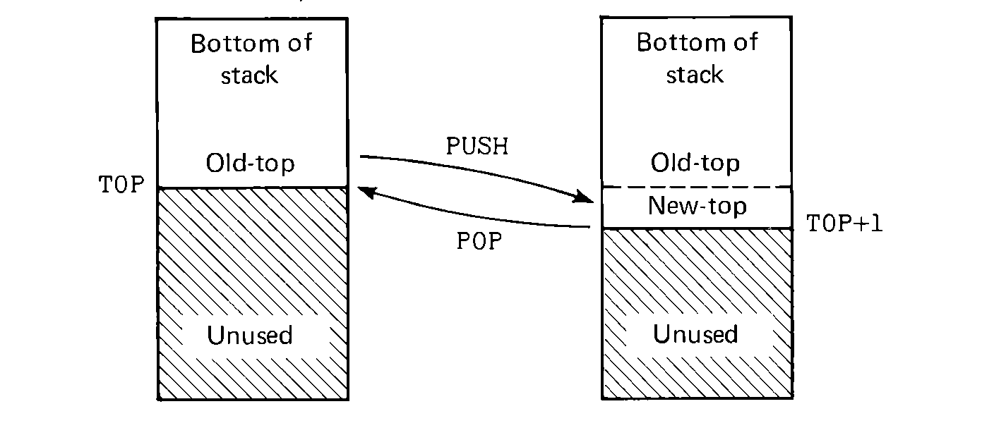 FIGURE 4.2 Stack operations: the
PUSH operation adds a new element to the top of the stack; the POP
operation removes it.
FIGURE 4.2 Stack operations: the
PUSH operation adds a new element to the top of the stack; the POP
operation removes it.
Two operations are possible on a stack: PUSH and POP (or STACK/UNSTACK, ADD/REMOVE, etc.). The PUSH operation involves adding a new element to the top of the stack. This requires storing the element on the top of the stack and increasing the number of elements by one. Assuming the element is in the A register and index I5 is not in use, the code for this would be,
This code checks to see that we do not store more elements in the stack than we have allocated space for. This type of error checking is good programming practice.
To remove an element from the stack and put it into the A register requires a similar sequence of code. This time we check to make sure that the stack is not empty before we remove an element from the stack. Also since the top-of-stack index (TOP) is the index of the next empty space in the stack array, we decrement it before loading the stack element.
In addition to arrays of multiple-word items, arrays may be of partial-word elements, and particularly of single characters (one byte). The techniques which are used for manipulating arrays of characters (called strings) are very important. One character requires one byte for storage, thus it would be very wasteful to use an entire word to store only one character. Also, certain I/O devices, such as the card reader and line printer, use character strings which are packed five characters per word. For computational purposes, however, we wish to use the string one character at a time, generally. This requires unpacking the string and extracting one character from it. Two techniques are commonly used on the MIX computer: partial field specifications and shifting.
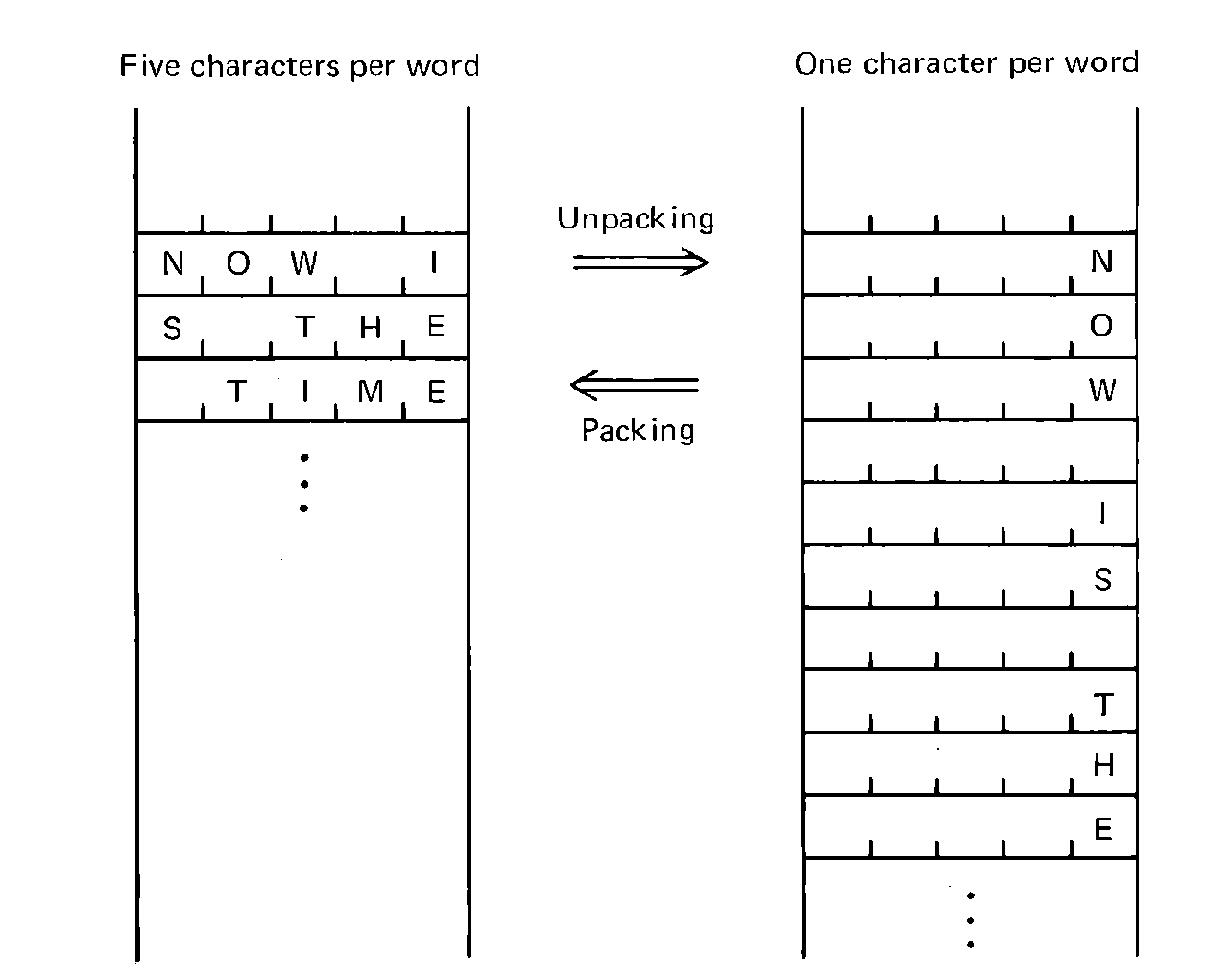 FIGURE 4.3 Packed and unpacked
strings of characters (characters must be packed for input and output, but
it is more convenient to program unpacked characters).
FIGURE 4.3 Packed and unpacked
strings of characters (characters must be packed for input and output, but
it is more convenient to program unpacked characters).
As an example, suppose we have an input card in the 16 locations CARD, CARD+1, …, CARD+15, and we wish to count the number of blank characters on the card. We want to examine each of the 5 bytes in each of the 16 words of the card. Letting index register 2 be our counter, we can write the following code to do this, using partial field specifications.
This is a very simplistic approach which has its advantages but is very tiring in terms of writing code. The only varying portion is the field specification of the LDA instruction. There are several approaches to shortening the code. One is through instruction modification. In this approach we notice that the field specification is stored in byte 4 of the load instruction and we want this to be successively (1:1), (2:2), (3:3), (4:4), (5:5). The following code does this by keeping in index register 3 the partial field we want to use and changing the LDA instruction for each execution of the loop.
This shortens the code but is more difficult to follow. The problem is that in debugging this code, the instructions which are executed are not the instructions which are written in the assembly program listing. You cannot tell by looking at the listing what the instruction which used to be LDA CARD,1(7:7) is in fact when it is executed. This makes it very difficult to debug a program and is considered a poor programming practice.
The more common approach to character manipulation is through shifting. Consider the word
| A | B | C | D | E |
| B | C | D | E | 00 |
| C | D | E | 00 | 00 |
| D | E | 00 | 00 | 00 |
| E | 00 | 00 | 00 | 00 |
Other shift instructions can be used to vary the position of the character which we are processing. If we load into the X register and SLAX 1 before processing, Then the characters appear in byte (5:5) of the A register for processing as
| A Register | X Register | |||||||||||
|
|
|
|||||||||||
| SLAX 1 | ||||||||||||
|
|
|||||||||||
| SLAX 1 | ||||||||||||
|
|
This approach is fine for processing the characters sequentially from left to right, but what if we need only the 37th character from the card? The 37th character will be in word CARD+7, byte (2:2). How do we access it? First, how did we determine its location? Looking at the card as it is stored in memory
| COLUMN OF CARD | 1 | 2 | 3 | 4 | 5 | 6 | 7 | 8 | 9 | 10 | 11 | … | 80 |
| WORD | 0 | 0 | 0 | 0 | 0 | 1 | 1 | 1 | 1 | 1 | 2 | … | 15 |
| BYTE | 1 | 2 | 3 | 4 | 5 | 1 | 2 | 3 | 4 | 5 | 1 | … | 5 |
| WORD NUMBER | = | (COLUMN NUMBER-1) / 5 |
| BYTE NUMBER | = | 1 + REMAINDER OF (COLUMN NUMBER-1)/5 |
Once we know the word number, we can use that as an index to load the appropriate word. Then, to get the correct byte we shift the loaded word so that the byte we want is in some convenient location (generally byte 1 or 5 of the A or X registers). For example, if we load into the X register and shift left the number of bytes which is the byte number (1, 2, 3, 4, or 5), the desired byte will be in byte 5 of the A register. To illustrate, suppose register I5 has the column number of the character we want. Then our code can be as follows. First, put the column number minus one in the X register and zero the A register for the DIV.
Once we have the word number in I2 and the byte number in I3, we can obtain the character we want by
The character is now in byte 5 of the A register. We could have put it in byte 1 of the A register by
Code such as the above allows us to specify characters by a character or column number, and hence ignore the packed nature of the characters in memory. However, notice that this takes a fair amount of computer time (the DIV instruction has the longest execution time of any instruction in MIX) and it also requires the use of both the A and X registers and two index registers. Thus, it may be better to break the processing of a card into two parts: first, unpack the card, and second, process the unpacked form. This allows the character number to be used as an index into the unpacked character array. After being processed, the data may need to be packed again for output.
Consider a program which reads a card and squeezes out all multiple blanks between the words on a card. The input might be English text which was prepared on a keypunch whose space bar sticks and sometimes inserts several blanks, between words. Our overall approach for the program could be to first read the card into a 16-word array CARD. Then it is unpacked into the 80-word array CHAR. From this array we move the card to an array OUTPUT without multiple blanks, and then finally pack it into an array called LINE for output (say to a card punch). Ignoring the actual input and output (which is the subject of Chapter 5), we can write the following code.
A very common form of character manipulation is lexical analysis. Many programs operate on character data which is constructed from free-format multi-character words or symbols. The words or symbols are separated by blanks, special characters, or other delimiters. To operate on them, it is necessary to group together contiguous characters into words or symbols. This is lexical analysis, or lexical scanning.
For example, the entire text of this book has been stored on magnetic tape. To insure that there are no spelling errors, a program was written which produced a list of all of the different words in this book. This list was scanned for misspelled words. To produce the list, it was necessary to scan a line of characters and identify where each word began and ended. Then these individual characters were packed into a single item and stored in a table.
Assume that no single word or symbol (called a token) is more than 10 characters long. It could be packed into the A and X registers, using shift instructions as shown in the last section. Then, to find all the words on a card, we could write a program such as
In this chapter, we have presented many different assembly language programming techniques. The techniques presented include how to compute arithmetic expressions, how to program conditionals and loops, examples of the use of arrays and tables, and some simple character manipulation techniques. Most of these concepts are easy and should quickly become a matter of habit. These are basic programming techniques; there are many others equally simple, and also a large number of more advanced techniques. The more practice you have in programming, the more skilled you will become at the art of assembly language programming. Additional programming concepts will be introduced throughout the remainder of this text.
Most assembly language programming techniques are developed by assembly language programmers by trial and error and are not written down for study. Many are passed from programmer to programmer informally, and many are picked up by reading the programs of a more experienced programmer. The program segments in the three volumes of The Art of Computer Programming by Knuth (1968, 1969, 1973) are good sources for MIX. Gear (1974) has a chapter on programming techniques, as does Eckhouse (1975). Stone and Siewiorek (1976) have many examples. In all cases except Knuth, however, these examples are for a computer other than the MIX computer. Thus, it is generally necessary to understand the computer instruction set and assembly language being used as the example language of that book before the programming techniques can be transferred to your MIX programs.